UTILIZING CHEMICAL TAGGING COMPOUNDS TO LOCATE GENERATOR HOT SPOTS
Masayuki Kawahata, Ph.D.
MEASUREMENT SERVICES DIV.
Steven Kilmartin - Utility Products Specialist
INSTRUMENTS DIV.
George Skala - Senior Engineer
INSTRUMENTS DIV.
I. ABSTRACT II. INTRODUCTION A. DESCRIPTION OF GCM OPERATION B. EVALUATING GCM ALARMS C. TAGGING COMPOUNDS D. NEED FOR TEST PROGRAM III. TEST PROGRAM A. TEST OBJECTIVES 1. GCM RESPONSE 2. COLLECTION OF TAGS 3. LABORATORY IDENTIFICATION OF TAGS B. TEST LOCATION C. DESCRIPTION OF TEST IV. TEST RESULTS V. CONCLUSIONS
Generator Condition Monitors (GCM's) and Core Monitors (CM's) have been providing unequaled margins of generator protection through early detection of overheating for several years. Although overheating can be reliably detected, determining the location of the hot spot has been a difficult challenge. Chemically and thermally stable Tagging Compounds have been devised enabling the specific area of overheating to be identified. The compounds are incorporated in trace quantities in protective coatings applied to critical areas of the generator. Prior to the development of Tagging Compounds, extensive tests had been conducted to characterize the pyrolysate of existing generator materials. Unfortunately, the pyrolysate products of these similar materials are very difficult to distinguish from one another. Tests were undertaken to determine: 1) if the GCM would respond to overheated Tagging Compounds, 2) if Tagging Compounds could be effectively collected following a GCM response and 3) if the Tagging Compounds could be identified in the laboratory. Earlier tests indicated that the GCM sampling system would need to be redesigned to allow for a larger sample to be collected to make laboratory analysis possible. In the tests, the GCM responded very rapidly to all overheating events, in most cases the alarm level was reached in less than one minute. However, as earlier tests had determined, it would be necessary to modify the sampling system to allow for a larger sample to be collected. The collection of a larger sample made it possible to identify the Tagging Compounds in the laboratory.
INTRODUCTION
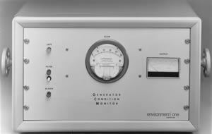
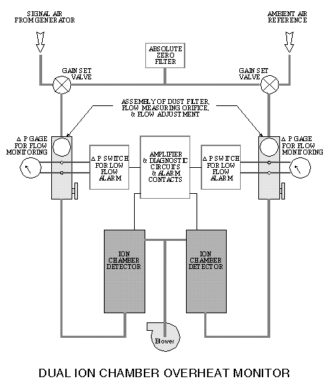
Most of the electrical power utilized in the United States is produced by large steam turbine generators. The value of power produced by one machine can exceed one half million dollars per day. It is therefore very important that any fault which might occur in the machine be detected and corrected promptly. The Generator Condition Monitor (GCM) and Core Monitor (CM) were developed to provide such detection. GCM's and CM's are now widely used and acknowledged by the power industry as a valuable device for providing early warning of "hot spots" in hydrogen cooled generators. The Generator Condition Monitor (GCM) is a sensitive real-time detector of submicrometer particles created by the incipient thermal decomposition of generator coatings and insulation. Particle detection is by means of an ionization chamber through which the hydrogen cooling gas is circulated by the pressure produced by the generator fan(s). Upon detection of the products of overheating, the GCM initiates an alarm verification sequence, triggers an alarm, and collects a sample of the particles for laboratory analysis.


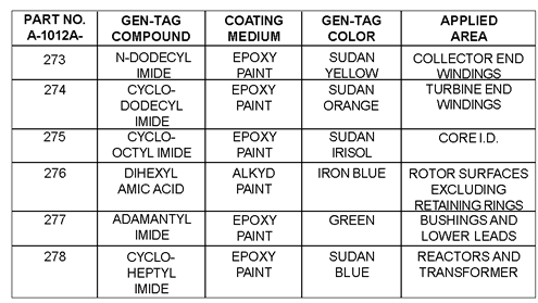
In trying to determine the location of the actual "hot spot", extensive work has been done to identify the specific products of thermal decomposition. This has proven to be a difficult task. Early attempts to trap gas phase pyrolysate using porous polymer adsorbents proved to be of little value since residual volatiles, which are normally present in the hydrogen coolant in the generator, mask the introduction of fresh volatiles produced by overheating. Collecting the particulate pyrolysate products on the proper filters will provide a sample that, when analyzed, will allow for laboratory confirmation of a GCM alarm. However, since many of the materials used in the generator (epoxy, varnish, etc.), give off similar pyrolysate products as determined by gas chromatography and mass spectrometry analysis, pinpointing the source of overheating is very difficult. To overcome the difficulty of characterizing the pyrolysates of existing generator materials, a new system employing Tagging Compounds has been devised by General Electric to provide a positive means of sensitive and definite identification of pyrolysate products. Several chemically distinct tags are incorporated in trace quantities in the protective coatings applied to critical areas in the generator.

The Tagging Compounds are designed so that the physical and chemical properties of the generator materials are not affected. Produced in encapsulated form, Tagging Compounds are thermally stable, allowing them to function over the service life of the generator. When overheating occurs the GCM automatically collects a sample of the overheated pyrolysate for laboratory analysis. Using a gas chromatograph with an electron capture detector the Tagging Compounds are easily identified and the location of the overheating determined. While Tagging Compounds can readily be overheated and accurately identified in the laboratory, field tests were necessary to satisfy any concerns over the ability to collect and identify them when overheated in an operating hydrogen-cooled generator. Extensive testing had been performed by Ontario Hydro regarding overheated generator materials and Tagging Compounds. Results of these tests had shown that the Generator Condition Monitor responds very rapidly to the overheating; however, when the pyrolysate sample was collected and analyzed in the laboratory positive identification of the tags could not be made. It was determined by Ontario Hydro that the pyrolysate sample being collected by the Generator Condition Monitor was not of sufficient quantity and not on the proper filters to allow for laboratory identification. To solve this problem a modified sampling system was designed and built by Environment One that would allow samples to be taken at various flows and using different filters. The test described here is one phase of the testing that was performed with Ontario Hydro in conjunction with Environment One's Measurement Service Division.
TEST PROGRAM
Before Tagging Compounds could be included as a component of the Generator Condition Monitoring System the following questions had to be answered:
1. Would the Generator Condition Monitor alarm when the Tagging Compounds were overheated in a hydrogen cooled generator?
2. Could the sampling system of the Generator Condition Monitor be redesigned to allow enough Tagging Compounds to be captured for laboratory analysis?
3. Could the Tagging Compounds be easily identified in a laboratory once collected?
Ontario Hydro has been performing operational field tests of Generator Condition Monitors and Core Monitors since late 1974. Most of the tests have been conducted on hydrogen-cooled generators at their Nanticoke Thermal Generating Station. To simulate generator overheating, a thin layer of insulating material was painted on 100 watt ceramic power resistors. A panel containing 24 resistors was fitted to a 540 MW turbine generator near the exciter end. Each resistor was connected to a current source through the instrumentation feed-through panel. A thermocouple was mounted on the surface of each resistor to determine the surface temperature. Resistors used for the Tagging Compound tests were coated with a thin layer of epoxy paint that contained trace amounts of the tags. Tests conducted earlier by Ontario Hydro proved that the Generator Condition Monitor responds very rapidly to the overheating, however, when the pyrolysate sample was analyzed in the laboratory no tags were found. It was also established by Ontario Hydro, through previous test burns, that a critical parameter in collection efficiency was the total flow through the assembly. To test different flows and filters a special test sampling fixture (figure 1) was built. The test sampling fixture allowed for up to three samples to be collected, utilizing collectors with various flow rates and loaded with different filters. Figure 2 illustrates how the test fixture was piped into the system. Listed is a description of the various filters used in the test.
Filters/Description Manufatcurer Material Pore Size Comments Gelman Glass Fiber Depth Filter Type A/E Millipore-FGLP Teflon 0.2 Millipore-HA Cellulose 0.45 GC Interferses Esters In Tag Analysis Nuclepore Polycarbonate .1 to 1 Flat Surface Millipore Silver 0.4 Suitable For SEM Analysis
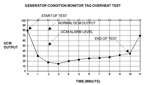
Ontario Hydro carried out several test burns using collectors having different flows and loaded with different filters. While most filters proved suitable for use in collecting tags, one filter interfered with the analysis. Since the Gelman glass fiber filter had been proven in the General Electric sampling system, it was decided By Environment One that its new sampling system would standardize using the same filter material. Having recognized that the total flow through the collector is one of the critical parameters in collection efficiency, burn tests were carried out with collectors having flows as low as 10 L/min (STP) and as high as 250 L/min (STP). It was established that satisfactory tag collection could be achieved at flow values of approximately 200 L/min (STP) for a sample time of ten minutes, to provide a total volume of approximately 2000 liters. It was apparent from these tests that changes would have to be made to the Generator Condition Monitor's sampling system and collector to ensure that the tags could be collected for laboratory analysis. First, the flow would have to be increased from, 10 L/min (STP) to approximately 200 L/min (STP). In order to accomplish this, the flow regulator and dampening restrictor would have to be removed and the sampler lowmeter replaced with one that could handle larger flows. Figure 3A is an illustration of the original sampling system and figure 4A is that of the modified sampler system. Since the original sampler collector had two filter holders and the test burns proved that only one filter is necessary, a modified collector was designed that would be loaded with only one filter. A nipple was included so that the collector was the same size as the original collector to make field retrofits easier. Figure 3B is of the original GCM sampler collector and figure 4B is of the modified GCM sampler collector. To prove that the modified sampling system could be retrofitted to the Generator Condition Monitor and that it would perform properly, a blind test was conducted between Ontario Hydro and Environment One. After modifying the sampling system in one of their Generator Condition Monitors, a resistor coated with epoxy containing a tag was overheated. The identity of the tag was known only by Ontario Hydro. Overheating of the resistor occurred within a few seconds after current was applied and continued for the length of the test (ten minutes). The signal (particulation) lasted as long as current was being applied to the resistor; however, particulation decreased in the latter minutes, since the coating was becoming completely pyrolyzed. Within a minute from the start of the test (overheating the resistor), the Generator Condition Monitor detected overheating and initiated sample collection. It should be noted that the GCM output, with no particulate present, is set at 80%. When the output drops below 50% the unit will go into alarm and initiate a sample. The overheating of the 100 watt resistor, with a surface area of approximately 10 cm2 caused the GCM output to drop to 15%, well below the alarm level. On the facing page is a chart that shows the Generator Condition Monitor output readings vs. time during the 10 minutes of overheating.

The Generator Condition Monitor began collecting a sample of the particulate when the output dropped below 50%. The sample collection period lasted for 10 minutes. When the sampling was completed, the sample collector was removed and taken to Environment One to be analyzed.
TEST RESULTS
At Environment One's laboratory, the glass fiber filter was removed from the collector and subjected to extraction using methanol. The extract was then concentrated before being analyzed using a gas chromatograph with an electron capture detector (GC/EC). Figure 5A is the gas chromatogram print-out of the sample burn collected at the station. Based on the closest retention time, the results indicate that the sample Tagging Compound is N-Dodecyl Imide, the tag that would be applied to the end windings. Test results were sent to Ontario Hydro which confirmed that the Environment One laboratory results (identifying N-Dodecyl Imide) were correct.
CONCLUSIONS
Three objectives were identified at the beginning of this test. The results of each are as follows:
- The GCM responds rapidly to overheated Tagging Compounds and a response well below the alarm set point is achieved from an overheated area as small as 10 cm2.
- Tests conducted by both Ontario Hydro and Environment One indicated that the Generator Condition Monitor sampling system needed to be modified in order to capture the Tagging Compounds. Generator Condition Monitors with the modified sampling system were capable of collecting a sufficient amount of tags for laboratory analysis.
- Blind tests indicated that trace amounts of Tagging Compounds incorporated in the generator material can be identified using a gas chromatograph with an electron capture detector.
ACKNOWLEDGEMENT
The work described was made possible due to the support of a number of organizations. Consolidated Edison Company of New York has partially supported the work pursuant to Generator Condition Monitors through Ontario Hydro, Canada.
|
Click here to download a PDF file |