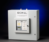
Generator Condition Monitor - Air-Cooled Apparatus (GCM-A 2)
Advancements in air-cooled generator designs have resulted in increasingly higher power ratings. The higher power densities place significantly greater stresses on materials and structures, making slight decreases in cooling efficiencies much more critical. Probability of overheating in these air-cooled machines becomes greater as designs are pushed closer to their critical limits.
The GCM-A2 warns of an impending failure much faster than RTD’s or thermocouples. Why? Because RTD’s and thermocouples need to be physically near the hotspot, or wait until overheating progresses to the point that the temperature near the RTD or thermocouple rises sufficiently for the sensor to detect it. This results in a significantly larger “fault,” possibly a catastrophic one. The GCM-A2, on the other hand, detects the pyrolysis particles emitted into the cooling air as a result of overheating or arcing virtually anywhere in the machine.
How the GCM-A 2 Works

The GCM-A2 monitors two air sample lines using a submicrometer particle detector. One line monitors ambient air, which serves as a reference. The other line is used to monitor generator cooling air, which is then compared against the particle level of the reference. High particle levels in the generator cooling air, without a corresponding increase in the ambient air, confirms the source of the pyrolysis particles is from within the generator.
In the event overheating occurs, large numbers of pyrolysis products are created in the generator cooling air. When the signal level corresponding to the difference between the generator cooling air and ambient air exceeds a predetermined (adjustable) set point, the result is a differential alarm, causing the alarm contacts to close. Individual contacts will also close if the outputs corresponding to the ambient air and/or generator cooling air exceed predetermined (adjustable) set points.
Download the GCM-A 2 brochure
GCM-A 2 Specifications
| MEASUREMENT CHARACTERISTICS | |
| Detection Principle | Submicron particle detector |
| Air Flow Rate | Adjusted by Zone Manifold, nominal 14 LPM |
| Readout (LED bar graph) | |
| Ambient Air | 0 to 100% scale |
| Generator Air | 0 to 100% scale |
| ELECTRICAL CHARACTERISTICS | |
| Power Input | 115 VAC, 50/60 Hz (230 VAC, 50/60 Hz optional) |
| Output Relays | |
| Ambient Alarm, Zone 1 | 3 A @ 120/240 VAC 3 A @ 30 VDC 100 mA @ 125 VDC |
| Generator Alarm, Zone 2 | |
| Differential Alarm | |
| Warning | |
| System Trouble | |
| Flow Trouble | |
| 4-20 mA outputs | 500 ohms max |
| Ambient Air | 4-20 mA = 0-100% |
| Generator Air | 4-20 mA = 0-100% |
| Differential | 4-20 mA = 0-100% |
| MECHANICAL CHARACTERISTICS | |
| Dimensions, overall | 24" h x 24" w x 11.75" d |
| (610 mm x 610 mm x 299 mm) | |
| Weight, approximate | 85 lbs (38.6 kg) |
| Connectors, gas inlet | 3/8" NPT, standard |
| Ambient temperature | 32-122 F (0-50 C) |
| Area Classification | Non-Hazardous |
| Relative Humidity | 0-95% |
| Controls | 5-key switch keypad with LED indicators and liquid crystal display |